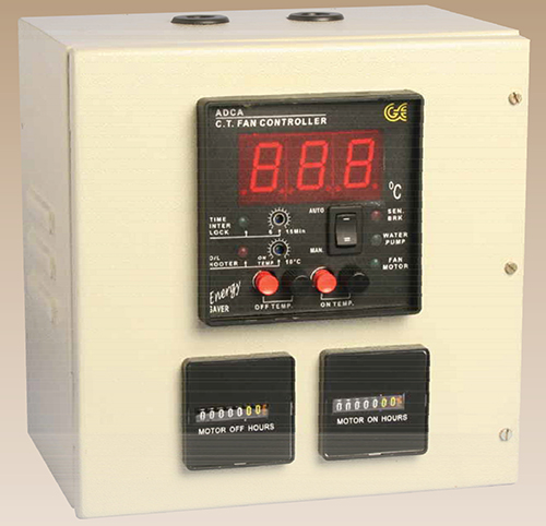
Cooling Tower Energy Saver


Cooling Tower Energy Saver
INTRODUCTIONCooling Tower Energy Saver is a Energy devices which controls the Fan Motor situated on the top of your Cooling Tower with respect to the temp. of the water in your tower tank. The ON temp., OFF temp. of the motor can be individually selected as per the desired application of your cooling tower. The unit has a auxiliary Relay and should be used in the control circuit. The output of switching Relay is 1C/O at 2A 230V rating (resistive). The unit works automatically and continuously without interruption. Incase of failure of the unit the Fan Motor automatically switches to run continuously as the Relay NC contact is used for this application. This controller can be used for any Cooling Tower of any make and any capacity used for any application. The higher the capacity of motor, the higher the savings.
Indications Of Front Panel1. MOTOR: 5mm Red LED Indicates whether the Fan Motor is ON.
2. WATER PUMP: 5mm Red LED Indicates whether the Water Pump (WLC) is ON.
3. SENSOR OPEN: 5mm Red LED Indicates whether the Sensor (RTD) is disconnected from the unit.
4. HOOTER: 10mm Red LED Blinking Indicates whether the Actual temp. has crossed hooter temp. setting.
5. ON HOUR METER: Indicates the No. of hours the Motor has RUN.
6. OFF HOUR METER: Indicates the No. of hours the motor has remained OFF.
7. DIGITAL DISPLAY :
A. Normally indicates the actual process temp.
B. When ON temp. switch is pressed the display indicates ON temp. set.
C. When OFF temp. switch is pressed the display indicates OFF temp. set.
D. When HOOTER temp. switch is pressed the display indicates HOOTER temp. set.
ON/OFF SETTINGS (FAN MOTOR) The Fan Motor can be controlled using the ON temp. & OFF temp. settings.
SETTING: Always ensure that the ON TEMP>OFF TEMP i.e. ON temp. is the temp. at which the motor is started to cool down the water and OFF temp. is that when the water has cooled to the required temp. and Fan Motor stops.
e.g. if the fan motor needs to start at 33ºC & stop at 31ºC, set as follows
ON temp. = 33ºC
OFF temp. = 31ºC
To set the ON temp. press the motor ON switch and rotate the motor ON knob, and similarly for OFF temp. Motor ON is indicated by the motor ON LED on the front panel.
4. RTD SENSOR
The unit is to be used with RTD sensor only. The RTD sensor is of PT-100 type in 2/4/5/6 feet long, fabricated in a special shape to avoid any water seepage. Also this RTD sensor is there wire type and hence if the wire normally provided (2mtrs) is short, any wire of similar type could be connected for extension. Mounting of this sensor is to be done with the adjustable sensor brackets provided, such that the sensor covers the best portion of your tank. This sensor can be dipped only upto the fixing nut & not above that. Please ensure that no physical damage to the sensor is done as this may damage the sensor permanently.
The unit has a built in 2 level water level controller which you can use in either Delivery logic or Suction logic, so that the water level in your water tank below the cooling tower is maintained in specific limits (levels). Alternatively this water level controller can also be used independently. Water level controller operates on electrical conductivity principle for controlling the pump operation at two desired water levels in your CT tank. The O/P of switching relay is 1C/O of 5A 240 VAC (Resistive). Water level controller can work in either Suction logic or Delivery logic by using suitable terminals either 12&13 (C3-NC3) or 11 & 12 (NO3-C3) respectively.
A. SUCTION LOGIC
When you select Suction logic by using output contact terminals 12 & 13 (C3-NC3) then the level sensing prods P1, P2, P3 are to be put into the underground water tank. The Pump Motor will Start automatically when the underground tank is full & will stop automatically when the tank is empty.
B. DELIVERY LOGIC
When you select Delivery logic by using output contact terminals 11&12 (C3-NO3) then the level sensing prods P1, P2, P3, are to be put into the overhead water tank. The pump motor will start automatically when the overhead tank is empty & will stop automatically when the tank is full.
